- 您现在的位置:买卖IC网 > Sheet目录1990 > BH2223FV-E2 (Rohm Semiconductor)IC CONV D/A 8BIT 10CH SSOP-B16
BH2223FV,BH2221FV
Technical Note
6/7
www.rohm.com
2010.06 - Rev.B
2010 ROHM Co., Ltd. All rights reserved.
●Notes for use
(1) Numbers and data in entries are representative design values and are not guaranteed values of the items.
(2) Although we are confident in recommending the sample application circuits, carefully check their characteristics further
when using them.
When modifying externally attached component constants before use, determine them so that they
have sufficient margins by taking into account variations in externally attached components and the Rohm LSI, not only for
static characteristics but also including transient characteristics.
(3) Absolute maximum ratings
Operating or testing the device over the maximum specifications may damage the part itself as well as peripheral
components. Therefore, please ensure that the specifications are not exceeded.
(4) GND potential
Ensure that the GND terminal is at the lowest potential under all operating conditions.
(5) Thermal design
Use a thermal design that allows for a sufficient margin regarding power dissipation (Pd) under actual operating
conditions.]
(6) Terminal shorts and mis-mounting
Incorrect orientation or misalignment of the IC when mounting to the PCB may damage part. Short-circuits caused by the
introduction of foreign matter between the output terminals or across the output and power supply or GND may also result
in destruction.
(7) Operation in a strong magnetic field
Operation in a strong electromagnetic field may cause malfunction.
(8) Power source voltage
Set the power source voltage so that VCC ≧ VDD.
(9) Reset Function
The power on reset circuit, which initializes internal settings, may malfunction during abrupt power ons. Therefore, set
the time constant so as to satisfy the power source rise time.
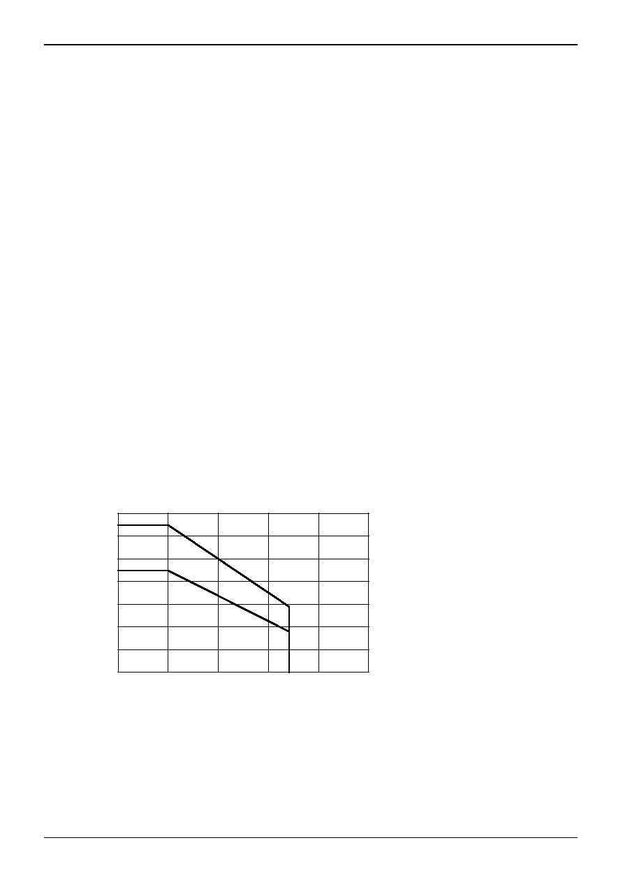
●Thermal Derating Curve
①SSOP-B20(BH2221FV)
②SSOP-B16(BH2223FV)
Fig.18
0
100
200
300
400
500
600
700
0
25
50
75
100
125
Ta [℃]
PD
[
m
W
]
Mounted on a 70x70x1.6mm FR4 glass epoxy board (copper foil area 3% or below)
①
②
发布紧急采购,3分钟左右您将得到回复。
相关PDF资料
BH2226FV-FE2
IC DAC 8BIT 8-CHAN SSOP-B16
BH2228FV-E2
IC DAC 8BIT 6-CHAN SSOP-B14
BQ4285EP
IC RTC W/114X8 NVSRAM 24-DIP
BQ4847YMT
IC RTC W/NVSRAM CONTROL T-MOD
BU2280FV-E2
IC CLOCK GEN DVD-VIDEO SSOP-B24
BU2363FV-E2
IC CLOCK GEN DVD-VIDEO SSOP-B16
BU2365FV-E2
IC CLOCK GEN W/VCXO SSOP-B24
BU2505FV-E2
IC DAC 10BIT 10-CHAN SSOP-B20
相关代理商/技术参数
BH2223GLU-E2
功能描述:数模转换器- DAC TUNING D/A CONVERTER RoHS:否 制造商:Texas Instruments 转换器数量:1 DAC 输出端数量:1 转换速率:2 MSPs 分辨率:16 bit 接口类型:QSPI, SPI, Serial (3-Wire, Microwire) 稳定时间:1 us 最大工作温度:+ 85 C 安装风格:SMD/SMT 封装 / 箱体:SOIC-14 封装:Tube
BH2226F
制造商:ROHM 制造商全称:Rohm 功能描述:Standard 8bit 8ch Type D/A Converters
BH2226F-E2
功能描述:8 Bit Digital to Analog Converter 8 16-SOP 制造商:rohm semiconductor 系列:- 包装:剪切带(CT) 零件状态:有效 位数:8 数模转换器数:8 建立时间:100μs 输出类型:Voltage - Buffered 差分输出:无 数据接口:SPI 参考类型:- 电压 - 电源,模拟:2.7 V ~ 5.5 V 电压 - 电源,数字:2.7 V ~ 5.5 V INL/DNL(LSB):±1.5(最大),±1(最大) 架构:R-2R 工作温度:-20°C ~ 85°C 封装/外壳:16-SOIC(0.173",4.40mm 宽) 供应商器件封装:16-SOP 标准包装:1
BH2226FV
制造商:ROHM 制造商全称:Rohm 功能描述:Expansion port function built in 8 Bit8chD/A converter
BH2226FV_09
制造商:ROHM 制造商全称:Rohm 功能描述:Standard 8bit 8ch Type D/A Converters
BH2226FV-E2
功能描述:8 Bit Digital to Analog Converter 8 16-SSOPB 制造商:rohm semiconductor 系列:- 包装:剪切带(CT) 零件状态:有效 位数:8 数模转换器数:8 建立时间:100μs 输出类型:Voltage - Buffered 差分输出:无 数据接口:SPI 参考类型:- 电压 - 电源,模拟:2.7 V ~ 5.5 V 电压 - 电源,数字:2.7 V ~ 5.5 V INL/DNL(LSB):±1.5(最大),±1(最大) 架构:R-2R 工作温度:-20°C ~ 85°C 封装/外壳:16-LSSOP(0.173",4.40mm 宽) 供应商器件封装:16-SSOPB 标准包装:1
BH2226FV-FE2
功能描述:数模转换器- DAC TUNING D/A CONVERTER RoHS:否 制造商:Texas Instruments 转换器数量:1 DAC 输出端数量:1 转换速率:2 MSPs 分辨率:16 bit 接口类型:QSPI, SPI, Serial (3-Wire, Microwire) 稳定时间:1 us 最大工作温度:+ 85 C 安装风格:SMD/SMT 封装 / 箱体:SOIC-14 封装:Tube
BH2226FV-F-E2
制造商:ROHM Semiconductor 功能描述: